TINY OFF-GRID HOUSE 20-AMP ELECTRICAL RECEPTACLES
CODE, INSTALLATION & OPERATION

Image Courtesy of Leviton
The most common and standard North and Central American, nondedicated, residential receptacle (Outlet) is a Single-Phase, 20 Amperage (Amp), 120VAC, 60 Hertz (Hz), duplex. The face of the receptacle has a short slot for the hot prong and a long slot, with lines in the shape of a capital letter “T”, for the Neutral prong, with an “U” shape hole for the ground prong. With the exception of 30 or 50Amp receptacles, all the interior electrical receptacles in the Tiny Off-Grid House will be 20 Amp duplex receptacles, grounded type (2020 National Electrical Code (NEC®) 406.4 (A), Tamper Resistant (Embossed with the letters “TR” on the face of the receptacle) (2023 NEC 406.12) — Simultaneous pressure has to be applied to the polarized slots in order to insert the plug.
According to The Electrical Safety Foundation International (ESFI) “Each year, approximately 2,400 children suffer severe shock and burns when they stick items into the slots of electrical receptacles – that is nearly seven children a day. It is estimated that there are six to 12 fatalities a year related to this. Nearly one-third of these injuries are the result of small children placing ordinary household objects, such as keys, pins, or paperclips into the outlets with disastrous consequences.”
The branch circuits conductors (Wire) for the 20 Amp receptacles will be no less than 12 AWG Copper.
RECEPTACLE ORIENTATION The standard orientation of receptacles with the neutral and hot facing up and ground facing down may not be the safest orientation of an energized receptacle; but does this really matter?
The Perfect Storm: An electrical cord is partially dislodged from a receptacle slot exposing the two energized prongs. The receptacle faceplate screw falls out or fails causing the conductive metal receptacle faceplate to fall striking the two energized prongs; resulting in an arc fault. Orienting a receptacle with the ground up and neutral & hot prongs down is probably the safest orientation because the conductive object would strike the ground prong.
Although probably safer, the ground up orientation is not practical for 90° plugs, which can compromise wire management.
Most residential electrical plugs are manufactured “without” a ground plug and with the hot prong located on the right side favoring a receptacle orientation with the ground slot facing down. The perfect storm scenario mentioned above with this type of electrical plug would be inevitable relying instead on an AFCI circuit breaker for fire prevention.
The potential for an arc fault with the receptacle oriented with the neutral & hot slots facing up can be mitigated with AFCI Plug-On Neutral circuit breakers. These circuit breakers will deactivate when an arch is detected.
At a minimum, all 20 Amp branch circuits in the Tiny Off-Grid House will be protected with AFCI Plug-On Neutral circuit breakers or where necessary, AFCI/GFCI Plug-On Neutral circuit breakers; in wet/damp areas. Also, the receptacle faceplates will be made of nonconductive plastic.
At the time of this writing, there are no recommendations or codes from the manufacturers of receptacles or the NEC, respectively, concerning the correct orientation of receptacles. So the orientation of the receptacle will mainly depend on what’s pleasing to the eyes of the consumer: maybe seeing the face of the receptacle with two eyes, one winking and a open mouth.
RECEPTACLE TERMINALS The standard receptacle has 2 sets of hot terminals with brass screws on one side and 2 sets of neutral terminals with silver screws on the otherside, along with a green grounding screw. There are 4 ways to connect conductors to a receptacle
SIDE WIRING: A section of insulation is removed from the conductor, then the bare wire is curved to resemble a hook (AKA: J Hook), which loops under the designated terminal screw in a clockwise direction. No insulation should come in contact with the terminals. The opening of the curved conductor should face the direction the terminal screw rotates to further tighten the terminal screw on to the conductor as the screw rotates clock-wise.
The advantage of screw terminals is better anchoring of the conductor to the terminal with >270 surface area contact between the conductor and terminal screw.
SPEED WIRING: Speed Wiring (AKA Back-Stabbing, Push-In) receptacles are manufactured (Exclusively) for 14 AWG solid conductors to be inserted and secured in to small holes in the back of the receptacles. Although Speed Wiring reduces labor during installation it is not the preferred method of securing wires to a receptacle for the Tiny Off-Grid House; even if it is UL approved. If the conductor is removed from the hole it can no longer accept another insertion securely. Also, the potential for the wires to loosen from vibrations or flextion are potential points of failure.
NOTE: If the Speed Wiring method is used, the unused screw terminals do not aid in securing the bare conductor and have to be recessed closed and not remain extended where they can come in contact with the metal receptacle box resulting in arching.
BACK WIRING: This method is found on most commercial grade receptacles; where the bare conductor is inserted under a compression plate which tightens down securing the bare conductor. The connection method is considered safe and secured as far as industry standards.
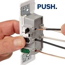
Image Courtesy of Leviton
NO SCREW TERMINALS: The new Leviton Decora™ Edge receptacle, with terminal levers, allows solid or stranded 12 - 14 AWG Cu conductors to be smoothly inserted in to the terminal and be secured by closing the lever with an audible click. No hot/neutral terminals are exposed. The No Screw Terminals has all the benefits of WAGO connectors eliminating the labor involved with —Side Wiring— screw terminals and exposed hot terminals. Each of the hot, neutral and ground terminal screws are replaced with color coded, audible locking, “levers.” The Leviton Decora Edge also comes with a built-in wire strip gauge.
The name Decora is a trade name by Leviton to describe their modern recepticle with a rectangular contemporary design.
SPLIT RECEPTACLE: A Split Receptacle is usually found in older homes without ceiling lights. The metal tabs between the hot terminals is removed to isolate each terminal. One receptacle remains on while the other, usually connected to a lamp, is controlled by a wall switch close to the entrance door.
BRANCH CIRCUIT CONNECTION TO THE RECEPTACLE There are two options for wiring an electrical outlet to the branch circuit: Pigtail or Through Wire. Pigtail wiring allows multiple wires to have one point of connection using a wire nut or WAGO connector. The Pigtail allows the receptacle to have an independent connection to the branch circuit, while a permanent conductor maintains connection to the branch circuit to provide power downstream. Even if the receptacle fails, there will be no interruption to the branch circuit power downstream.
The Through Wire technique uses the receptacle to continue the branch circuit connection downstream; by connecting hot/neutral conductors on the receptacle to their receptive brass/silver terminals while other hot/neutral conductors exits the receptacle from their respective terminals continuing power to the branch circuit downstream. However, the grounding conductor will still need to be wired Pigtail because most standard receptacles only have one screw/lever terminal. The one caveat with Through Wiring is if the receptacle should fail, power to the branch circuit downstream will be interrupted.
Both wiring options are approved by the NEC and receptacle manufacturers. The main advantage of the Pigtail is that there is no interruption to power on the branch circuit if the receptacle should fail. Also, the use of WAGO connectors should greatly decrease labor. The Tiny Off-Grid House will use Pigtails, with WAGO connectors, on all receptacles and switches; where applicable.
SWITCH RECEPTACLES A Side Tab on the hot/neutral sides of the receptacles bonds their respective pairs of screw terminals. If the Side Tabs are removed, the screw terminals are isolated from each other creating a Switch Receptacle. Switch Receptacles were common in older homes, with no ceiling lights, to control receptacles powering floor lamps. Most modern homes have ceiling lights powered by branch circuits delegating lamps for task or ornamental lighting.
RECEPTACLE LOCATIONS The Tiny Off-Grid House wiring design follows the NEC Codes for a standard U.S. home. In some cases, the Tiny Off-Grid House will exceed the NEC Code to enhance safety and energy efficiency. The locations of the receptacles will depend on their respective NEC Codes.
KITCHEN: A minimum of two AFCI/GFCI Plug-On Neutral 20 Amp circuits will service the Tiny Off-Grid House countertop 2020 NEC 210.52 (B)(C). According to the NEC, Kitchen countertops require at least two branch circuits. The two branch circuits even the electrical distribution of the kitchen appliances. If a kitchen counter top is 12” or wider, it must have at least one AFCI/GFCI receptacle. Inaddition, there must be a receptacle every 48” — linear, not diagonally; with a maximum height of 20” from the countertop surface. No section of the countertop should be more than 24” from a receptacle — Half of the NEC 48” spacing— since the electrical cord on most kitchen appliances is no longer than 24”. This discourages extending the electrical cord over the sink or range. A receptacle will be installed at each countertop work station; 24” from each side of the sink basin edge. NEC 210.52 (C)(1). None of the receptacles can exceed 4’ spacing between them; measuring along the linear wall, not diagnoly.
ROOMS/LOFTS: A receptacle is required within 6’ (1.8 m) of a room door/entrance, on both sides; then add an additional receptacle every 12’ (3.7 m) from the initial receptacle. A home office may require the installation of an additional receptacle(s) for convenience an additional 2’ (600 mm) from an adjacent receptacle
BATHROOMS: An AFCI/GFCI protected receptacle within 3’ of the outside edge of the sink basin
WALLS: A wall >24’ L requires a receptacle
WET/DAMP LOCATIONS: Read GFCI receptacles below
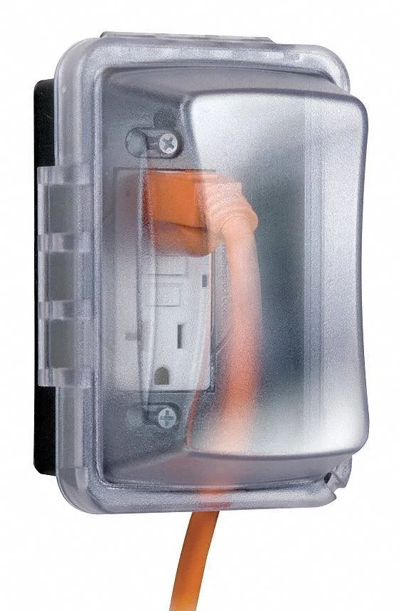
Photo Courtesy of HomeDepot
GFCI PROTECTED RECEPTACLES Receptacles installed in wet/damp locations like the water treatment module or outside of the Tiny Off-Grid House must be GFCI protected. Exterior weather resistant receptacles (Embossed with the letters “WR” on the face of the receptacle) require a non-corrosive, non-conductive electrical box along with a bubble receptacle cover identified as “Extra Duty” (2020 NEC Section 406.9 (B) (1)) to keep the electrical enclosure water resistant; even while “in-use.” The cover has a gasket that seals the openings and edges against water penetration (2011 NFPA 70).
Where ever a GFCI receptacle is required, the Tiny Off Grid House will use plug-on-neutrals GFCI with a combined Arc-Fault Circuit Interrupter (AFCI) —Dual Function— “circuit breaker”, located in the main service panel (MSP), instead of installing multiple GFCI’s “receptacles” at each point-of-use.
Note: A GFCI “circuit breaker” can not be used along with a GFCI “receptacle” at point of use; that would be redundant, only a standard electrical receptacle can be used if a Dual Function circuit breaker is installed in the MSP.
For more information on AFCI/GFCI protection please read “Tiny Off-Grid House Over Current Protection Device.”
Please share your thoughts or experiences in the Comments section below.